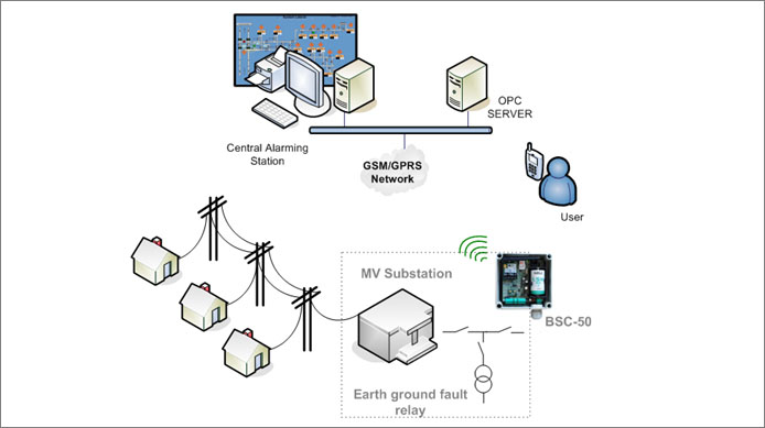
Medium voltage substations require monitoring in order to help power grid operators re-establish power, when network faults occur. Identifying a substation that is out of power is time critical to minimize operations to link back power on the grid.
Modern substations are equipped with earth fault detection relays (EFI or GFI, Earth or Ground Fault Indicator), which provide a digital contact when a line fault occurs. The goal is to reduce drastically the outage time. The normal procedure when a fault is detected is to send maintenance crew to visit a series of substations, identify the stations, which have a fault status and report this back to the control center. Then operations to reroute power are made remotely or on a trial and error basis, which damages the network infrastructure.
Requirements
- Identify faults almost online and alert via SMS to a control center.
- Minimize needed power rerouting operations.
- Identify operational faults from substation equipment.
- Manual operations alarming.
- Intruder security alarming.
Proposal
BSC-50E and BSC-50D battery powered RTUs are ideal for alerting using SMS. The proposed system consists of:
- Special fault detection relays that detect ground fault and provide a plain contact as an alert in the event of a fault.
- BSC-50D or BSC-50E devices which are installed to monitor the alarm state on medium voltage substations.

When an earth fault is detected in a substation the result is that the substation is automatically taken off the power grid. Manual or remote operations are needed to place the substation back on the grid. The BSC-50 devices monitor earth faults and transmit respective coded messages via SMS to a control center. Moreover BSC-50 RTUs can be configured to transmit a health message in a scheduled manner to the control center to ensure their operational status.
At the control center a PC running 24/7 software, logs alerts, monitors and reports the operational status of the BSC50 devices. Integration to existing SCADA systems or GIS applications is seamless via an OPC server.
M2M solution
Furthermore, as an extension utilizing M2M functionality, SCOM-100 devices can be used at the control center in order to have an unmanned system. In this case, at the control center, a mimic diagram showing the geographic location of the substations and BSC-50 devices is installed. The mimic diagram has built in colored LED at each substation. The LEDs are cabled to an M2M (machine to machine) alert receiver device as an SCOM-100 unit. The LEDs are connected to digital outputs on the SCOM-100. When an alarm occurs at a BSC-50, two messages are send, one at the control center monitoring station running the monitoring SW and one to the SCOM-100 device switching a LED at the mimic diagram.If the fault is rectified, the LED can be switched off via a manual operation of a switch on the mimic diagram (alarm acknowledgement and rectification). In this way users at the control center can,
- Visualize the location of the line faults.
- Trace the sequence of failing substations.
- Perform remote switching operations (if this is possible in respect to a local substation automation), or to order maintenance crew to visit a specific point on the grid to reroute power and maintain power in the areas which had been taken off the grid.
For example a BSC-50D alerting instantly and sending a health message every week, will operate on one Lithium Thionyl D type battery for more than 12 years.
Why BSC-50
- All-in-one cellular GPRS quad band solution
- Ultra low power, can run for years on one D type battery
- Real-time alerting
- Easy to implement and maintain
- Seamless connection to SCADA via OPC server
- SMS alerts and M2M functionality
Read more at,
